01 · Question
When does a tripod pose have static support?
I wanted measurements that could distinguish static support from visual appearance. The robot and ballast share one combined center of mass, and gravity acts downward through that point. The active foot-ground contacts define a support triangle. Projecting the center of mass vertically onto the ground shows where gravity’s line of action falls relative to that triangle.
02 · Prediction
The centered ballast should remain inside the support triangle.
For the centered 0.45 kg baseline, I expected the center-of-mass projection to remain inside the triangle, all three feet to retain positive normal contact load, and the body to stay nearly level. That prediction applies only to this baseline. I did not record a clean prediction for a corrected attached-ballast sweep.
03 · Experiment
Measure static support instead of trusting a pose.
The MuJoCo model had a free-moving torso and three articulated legs. Its leg motors reused the test bench’s existing controller to hold the intended tripod posture, so this was a static-support test under that controller rather than passive equilibrium. Each run recorded the combined center of mass, its ground projection, active foot-ground contact state, normal contact load at each foot, distance to the nearest support-polygon edge, body orientation, angular velocity, and body height.
The viewer overlaid a translucent no-ballast reference for inspection. The numerical report supplied the evidence.
04 · Observation
The centered baseline behaved as predicted; the later sweep did not survive inspection.
The centered 0.45 kg baseline retained all three foot-ground contacts. Its center-of-mass projection stayed inside the support triangle, and its roll and pitch remained near zero during the fixed-duration run.
I later varied a forward ballast from 1 to 100 kg. The results seemed to show a sharp tipping threshold, but the viewer exposed a configuration error. I had entered the ballast height as a world coordinate even though MuJoCo interpreted it relative to the chassis. The ballast was suspended far above the robot instead of resting on top of it.
05 · Model update
The active feet define the support region.
The active ground contacts form a support polygon. With three feet down, that polygon is the triangle joining them. In quiet static equilibrium on level ground, the upward forces at the feet must add up to the robot’s weight, and their moments must cancel the moment produced by gravity. That balance is possible while the center-of-mass projection lies inside the triangle or on its boundary.
If the projection passes beyond an edge, balancing the robot would require the opposite foot to pull downward on the ground. A normal contact force cannot pull, so that foot unloads. The two contacts along the crossed edge can then become a pivot, and gravity produces a tipping moment about that edge.
This is the mechanics model for the next experiment. Part 1 did not verify that sequence with a correctly attached ballast.
06 · Continuation boundary
Practice first; resume the experiment afterward.
Before running another treatment, I need practice with static equilibrium, one-way contact forces, moments about a pivot edge, and rigid-body angular velocity. I will use problems from the second edition of Daniel Kleppner and Robert Kolenkow’s An Introduction to Mechanics. That practice prepares Part 2; it is not Part 2.
Part 2 starts afterward, with a new prediction and a ballast position specified relative to the chassis. Until then, the experiment remains open. Neither this tripod fixture nor C-1N has established robust stance stabilization with an attached ballast.
07 · Follow-up evidence
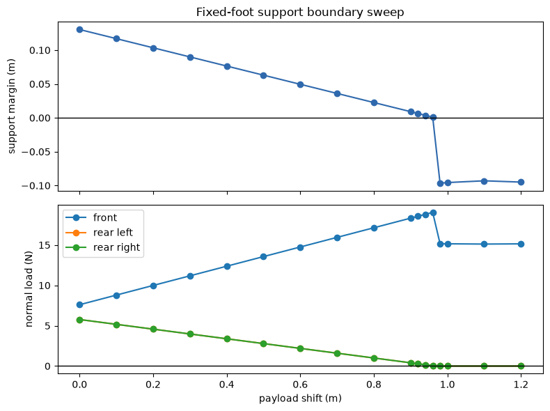
The fixed-foot sweep bracketed the support boundary.
The later fixture kept the three foot contacts fixed and moved only an explicit 0.60 kg payload along the body’s forward axis. Each condition ran for two seconds. At +0.96 m, the signed support margin was +0.0010 m and each rear foot carried 0.046 N. At +0.98 m, both rear contacts had unloaded and the final margin was -0.0965 m after the body tipped.
This brackets the transition between those sampled shifts. It corrects the initial expectation that margin exhaustion would arrive before rear unloading: in this fixed-foot fixture, the boundary was consistent with rear-contact unloading. It does not establish C-1N morphology, standing control, or gait stability.
Evidence & provenance
Canonical record
- Source issue #24 · static support ↗
- Fixed-foot boundary experiment · pinned commit ↗
- Executed Jupyter notebook · pinned commit ↗
- Portfolio evidence snapshot →
- Part 1 experiment record and stopping-boundary commit ↗
- Part 1 observation and decision record ↗
- MuJoCo passive-viewer documentation ↗
- MuJoCo upstream viewer loop ↗
- Kleppner & Kolenkow, 2nd ed. ↗